üüüüüüüüüüüüüüüüüüüüüüüüüüüüüüüüüüüüüüüüüüüüüüüüüüüüüüüüüüüüüüüüüüüüüüüüüüüüüüüüüüüüüüüü
ü@Strength of C-hook decreases gradually by ügmetal fatigueüh for several years over several decades depending on the frequency of loading. When the strength of C-hook falls below the stress by loading, it has the risk of breakage to cause a disaster. To avoid this risk, it is essential to design C-hook to have enough strength even after ügmetal fatigueüh.
ü@However, there are not a few C-hooks that seem to be designed and manufactured without considering the stress distribution or fatigue. An example of diagnosis of C-hook is shown below.
éPüDMetal fatigue
ü@Strength of steel material decreases gradually by repeated loading (metal fatigue), until it stops at the repetition of about 107 times of loading. After this, the steel material has the constant strength, which is called ügFatigue Limitüh. Fatigue Limit varies from 1/2 to 1/10 of the initial Strength, depending on the following factors.
ü@ü@ć@Segregation of chemical elements or inner defects of the steel material
ü@ü@ćAThermal strain by welding
ü@ü@ćBNotches or rough surface at the corner
ü@ü@
ü@As the decreasing strength of the actual C-hook by every loading cannot be measured, it must be presumed from those data of the initial strength and the fatigue limit of the steel tested at laboratory.
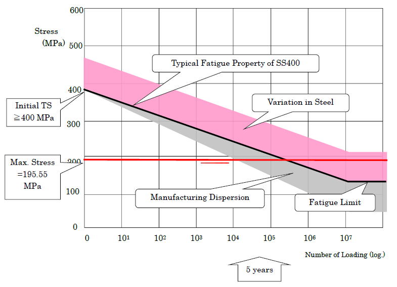
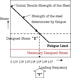 ü@If C-hook is designed at the stress level of "X" in the right graph, this C-hook has a risk of fatigue fracture around the loading frequency of ügYüh.
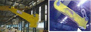
ü@Photos below show the results of such fatigue fracture.
ü@To avoid the fracture, it is indispensable to design the C-hock so as the generated maximum stress is below the fatigue limit.
 éRüDMethod of Diagnosis
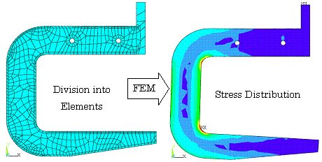
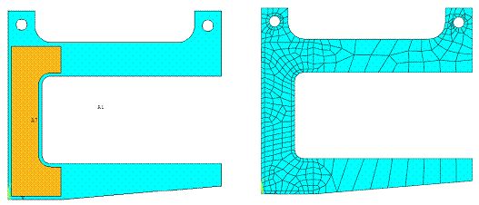
ü@The stress distribution, generated in the C-hook by loading a coil, is analyzed by "Finite Element Method" (FEM), where the C-hook is divided into small elements, as shown in the right figure, and these elements are related each other by formulas and analyzed by computer to obtain the stress distibution.
ü@FEM was invented and developed by Boeing Co. in USA for designing of airplane.
ü@Nowadays, it is widely used for designing of various machinery as well as building.
éSüDNecessary strength of steel material
ü@The fatigue property of the steel material can be measured only by test pieces in laboratory, not by the actual C-hook. Accordingly, it is necessary to take ügsafety factorüh into account to absorb the various differences between the actual C-hook and its theoretical design.
ü@The ügsafety factorüh includes
ü@1) dispersion of the tensile strength of the material,
ü@2) dimensional deviation in production,
ü@3) the heat treatment conditions and
ü@4) the deflection of the fatigue property.
ü@The average fatigue limit is around forty percent (40%=1/2.5) of its original tensile strength. Other factors shall be taken into account as the safety factor of around two (2).
ü@So the total safety factor against the original tensile strength of the material shall be
ü@ü@ü@ü@ü@ü@ü@ü@2.5 x 2 = 5,
which means the maximum designed stress in the C-hook should be below one fifth (1/5) of the initial tensile strength of the material.
éTüDExample of analysis
ü@Flat plate type C-hook as shown below, is taken up, which is used comparatively widely in the world.
1) Size of the C-hook
ü@The thickness of the main body is 90mm and 12 mm thick plates are welded on both sides for rainforcement.
ü@ü@ü@ü@ü@ü@ü@
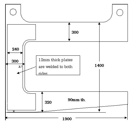
2) Loading capacityüFmaximum 20 tons
 3) Material steel grade
ü@SS400 (initial tensile strength üå400 MPa)
4) Analysis of generated stress by loading
ü@The right figures show the diagram and the elements of this C-hook input to the computer for the FEM analysis.
The stress distribution generated in the C-hook by loading 20 ton (196,000 N) coil, is as in the figure below. The maximum stress is 195.55 MPa at the upper and lower inner corners.
ü@ü@ü@ü@ü@ü@
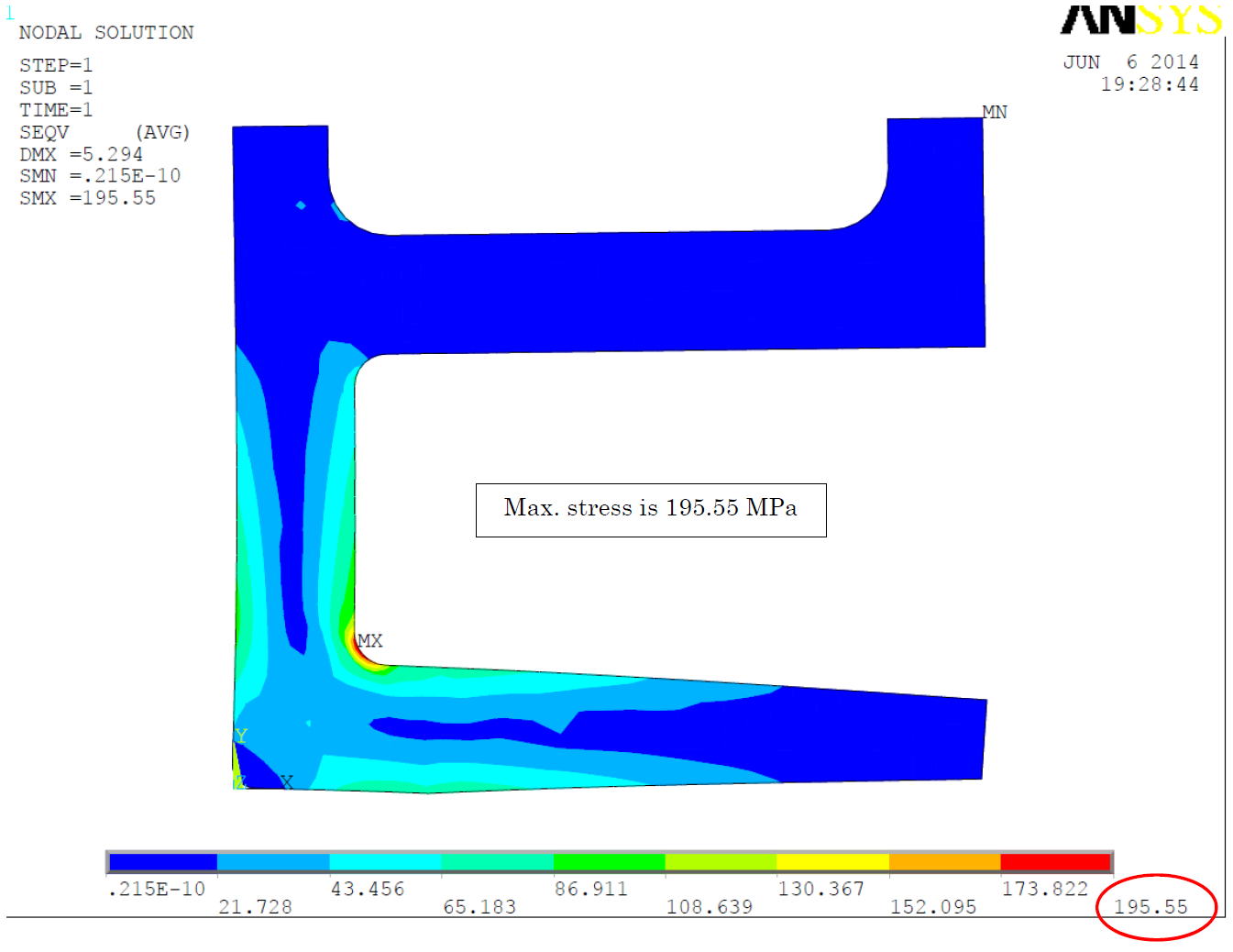
ü@There is a possibility that crack originates from these parts when strength of the steel material decreases by fatigue below this stress.
5) Strength of steel material
ü@Initial tensile strength of SS400 is over 400 MPa (41 kgf/mm2).
6) Calculation of safety factor
| ü@Maximum stress a |
Initial tensile strength b |
Safety factor b/a |
Assessment of safety | |
| 195.55 MPa | 400 MPa | b/a=2.0 | This C-hook has a risk of breakage as fatigue progresses. |
|
éUüDConsideration
1) Process of fatigue
ü@In case, this C-hook handles 10,000 tons monthly, where coil weight is 10 tons on average, this C-hook loads 10,000/10=1,000 times monthly, which means 12,000 times annually and 6ü~104 times in 5 years.
ü@Rough image of the relations among the fatigue properties of the C-hook, the maximum stress added by loading and the effect by manufacturing dispersion is shown in the following figure.
ü@After aound five years of operation, this C-hook will enter into the colored risky zone.
ü@ü@
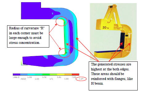
2) Effects of structure
ü@The cross-sectional configuration should be based on the stress distribution generated in the C-hook, as shown in the figures below, to decrease the deflection of the stress.
ü@ü@ü@ü@ü@
 ü@
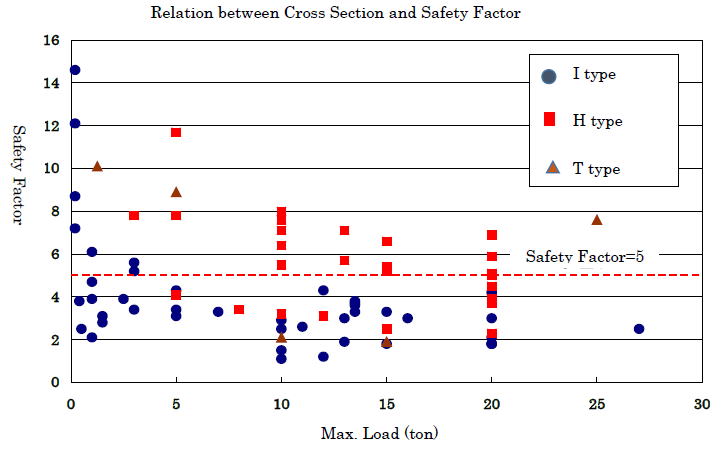
ü@The figure below shows the safety factor of C-hooks with various cross sections, based on the results of diagnosis of the maximum stress at maximum loading weight. Flat type C-Hook (ü£) is difficult to secure the safety factor of five (5) comparered to H type (üĪ) .
ü@
üüüüüüüüüüüüüüüüüüüüüüüüüüüüüüüüüüüüüüüüüüüüüüüüüüüüüüüüüüüüüüüüüüüüüüüüüüüüüüüüüüüüüüüüüü
HOMEü@ŗZÅpÄæŚ┐Ä║